
Sand and Gravel Separator Chute Fabrication: Key Design and Manufacturing Insights
2026-08-22
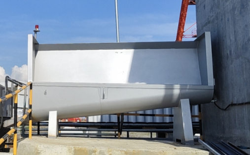
Every sand and gravel operation eventually learns the hard way that a separator chute is not just a piece of bent steel. It is the point where abrasive slurry meets structural design, and small fabrication missteps turn into daily downtime. Too often, the chute becomes an afterthought until cracks, plugging, or liner washout force a closer look. Here, we break down the design and manufacturing details that make the difference between a chute that survives and one that fails early. The insights are grounded in real shop and field experience, not theoretical models. For operations that cannot afford unplanned stops, Sinou brings a fabrication perspective built on hundreds of separator chutes.
Get the Drop Angle Right Before You Cut Steel
Setting the torch dead vertical might feel like the safe choice, but it often leaves dross hanging off the bottom edge. A slight forward tilt—around 5 to 10 degrees from vertical, with the tip leaning into the direction of travel—changes everything. This drop angle lets the oxygen stream drive molten steel through the kerf instead of letting it puddle and re-solidify. Test the feel on scrap first; when the angle is right, the slag sprays downward in a tight, steady cone rather than spitting back at your gloves.
Going too far with the tilt creates its own mess. The top edge gets undercut, the cut face looks slanted, and the bottom carries a heavy line of fused dross. If you hear a sharp popping noise or see sparks bouncing off the plate surface, ease the torch back a degree at a time. The sweet spot usually sits where the cutting stream exits the steel almost straight down, with just enough forward bias to keep the kerf clear.
Before touching your actual workpiece, run a short cut on a piece of the same thickness. Watch how the slag falls—if it exits the bottom at roughly 30 degrees past vertical and leaves a clean, narrow kerf, you’re close. Adjust for tip size and travel speed, then lock your wrist and commit. A correctly set drop angle means less grinding, fewer wasted blanks, and a cut edge that needs almost no cleanup.
Why Liner Bolts Fail More Often Than the Liners Themselves
The liner itself is a thick slab of hardened steel, designed to absorb repetitive impact and abrasive wear. Bolts, by contrast, are slender, threaded fasteners forced to perform a job they were never meant to do alone: holding a massive, vibrating liner against a rotating mill shell. Every revolution of the mill flexes the liner just enough to transfer stress directly into the bolt's thread roots, where microscopic cracks start almost immediately. The liner's mass protects it from this kind of concentrated fatigue, but the bolt has nowhere to hide.
Another overlooked factor is the uneven load distribution across a bolt circle. As the mill turns, ore and grinding media pile up on one side, creating a powerful bending moment that shifts constantly. Liners absorb this as broad, distributed pressure, but a single bolt can experience tensile spikes far beyond its rated capacity. Over time, the threads yield, the shank stretches, and the bolt loses preload. Once preload drops, the liner begins to work against the bolt, hammering it with every cycle until it snaps.
Corrosion also plays a quieter but equally destructive role. Pulp and acidic slurry seep between the liner and shell, attacking the exposed threads and the underside of the bolt head. A liner's wear surface faces the ore, but its backside stays relatively dry and protected. The bolt, however, sits in a wet, oxygen-starved crevice where pitting and stress corrosion cracking thrive. What looks like a sudden failure on the outside is often the result of months of electrochemical attack inside the hole.
Fabricating Discharge Lips That Won't Crack After One Season
Most discharge lips crack because the bolt holes are punched cold and left with sharp edges. Stress concentrates there during the first freeze-thaw cycle, not from impact with the ground. I start with an 85A durometer polyurethane blank, but the real fix is undercutting each hole slightly and pressing in a steel sleeve before the lip ever bolts to the moldboard. The sleeve takes the clamping load, while the polyurethane around it stays in compression instead of tearing.
The second failure point is the lip being forced to flex beyond its natural radius right after installation. I cut the blank 6 percent longer than the housing, clamp it to a wooden form that matches the final curve, and leave it in a heated shop overnight. Once the material has relaxed into that shape, I drill the holes through both the lip and a 10-gauge stainless backing strip. The strip spreads the load and prevents the holes from elongating. After the first heavy use, I retorque the fasteners with the lip under load, which stops the creep that normally shows up as cracks around the washers by late fall.
Using Replaceable Wear Bars Instead of Hardfacing Repairs
Traditional hardfacing repairs demand significant downtime, skilled welders, and repeated passes to build up worn surfaces. In many applications, those hours add up quickly, yet the restored area still wears down faster than the surrounding base metal. Replaceable wear bars flip that logic on its head: instead of rebuilding material layer by layer, you swap out a sacrificial component that's designed to take the abuse. This shift turns a rebuild into a routine replacement, often completed in a fraction of the time with no welding required.
The real advantage shows up in high-abrasion zones like conveyor beds, bucket interiors, or chute liners. A bolted or clamped wear bar allows operators to rotate, flip, or replace individual sections as they wear unevenly. You avoid the heat-affected zones and distortion that come with welding, and you keep the original structure intact. Maintenance crews can schedule short change-outs rather than lengthy repair campaigns, and inventory becomes predictable: keep a few spare bars on the shelf instead of relying on specialty welding rods.
Cost comparisons often overlook the hidden price of hardfacing—preheating, interpass temperature control, post-weld cleanup, and the inevitable re-repair when cracks propagate through the overlay. Replaceable wear bars eliminate those variables. They also make it easier to experiment with different materials, such as hardened steel, chromium carbide, or ceramic-embedded compounds, without committing to a permanent metallurgical change on the original part. Over time, the parts that used to be rebuilt repeatedly become like a set of tires: rotate, replace, and keep the machine running.
Designing for Cleanout Without Adding Extra Flanges
A cleaner piping layout often avoids dedicated flanged cleanout fittings by making a short spool piece removable. This spool can be connected with threaded unions or grooved couplings on both ends, so the section lifts out in seconds. The real trick is placing these break points where a worker can actually reach them without climbing over equipment or disconnecting adjacent lines.
Another practical route is to swap in a standard tee or wye that already has a plugged branch. Instead of adding a separate flange pair for access, the plug itself becomes the cleanout port. For lines that need frequent flushing, using a bend with a removable cover plate or a quick-release clamp keeps the opening compact and avoids the bulk of a flange.
When you design this way, the cleanout opening should match the full pipe bore so debris doesn't collect behind a shoulder. Every removable joint needs a gasket or seal that can be reused without losing pressure integrity. Done carefully, the cleanout becomes part of the pipe routing itself, not an extra component bolted on.
Reading Worn Chute Surfaces to Improve the Next Build
Inspecting the wear marks left on a chute after months of service tells you things a CAD model never will. Localized gouges near the impact zone usually mean the material stream is hitting harder than the liner was meant to absorb, while a smooth, polished strip along one side often points to a slight misalignment in the feed. Rather than treating these as routine damage, we treat them as field data: each scratch and worn edge shows how fines and larger particles actually move through the drop.
That feedback loop changes the next build before a single plate is cut. If the wear pattern shifts toward the outside of a bend, we adjust the radius or add a sacrificial wear bar exactly where the abrasion concentrates. When the bottom plate shows thinning but the side walls stay untouched, we reduce plate thickness in the unused areas and reinforce the floor instead. Small changes like these—based on what the old chute is already telling you—cut replacement downtime and keep the next liner budget closer to where it should be.
Over time, this habit of reading worn surfaces becomes part of the design process itself. The goal is not a chute that never wears, but one that wears predictably and inexpensively. A carefully studied worn chute is often a better starting point than a blank screen, because it carries the accumulated behavior of real material, real moisture, and real operator adjustments that no simulation fully captures.
FAQ
Abrasion-resistant steels like AR400 or AR450 are common for the main shell, while polyurethane or rubber liners can absorb impact in high-wear zones. In wet, corrosive environments, stainless steel may be worth the extra cost.
Too shallow and material stalls or builds up; too steep and the mix slides too fast for proper sorting. Most designs land between 35 and 45 degrees from horizontal, adjusted for moisture content and particle size.
Liners take the punishment instead of the structural shell, so they can be swapped during scheduled downtime without cutting and re-welding the main chute. This extends overall service life and lowers long-term fabrication costs.
Avoiding sharp inside corners, using full-penetration welds at high-stress joints, and stress-relieving the assembly after welding help. Adding gussets at mounting points also spreads impact loads.
Sectional construction is usually better for large chutes because it simplifies transport, allows replacement of damaged areas, and makes shop fit-up easier before field assembly.
Design the chute so the material stream hits a sacrificial wear plate or rock box first. Field experience often guides extra thickness on the primary impact face while keeping other areas lighter.
Dimensional checks against the hopper and screen inlet, weld inspection for cracks or undercut, and confirming liner bolt patterns align correctly before installation.
Conclusion
In sand and gravel separator chute fabrication, the difference between a chute that runs for years and one that needs constant welding comes down to decisions made before the first cut. Getting the drop angle right is not just about material flow; it determines impact zones, wear patterns, and whether fines will build up in dead spots. Once steel is cut and fit, correcting a bad angle means costly rework, so mock-ups and cardboard templates are worth the time. Liner bolt failures, for example, are rarely about the bolt itself. The real culprits are usually slight movement between liner and shell, undersized bolt holes, or lack of a compressible backing that lets impact energy rattle everything loose. Tightening a bolt harder does not fix that. Similarly, discharge lips crack after one season because the detail drawings treat them as simple flat bars welded to the chute floor. Without a radiused transition, proper root gap, and controlled preheat, the weld shrinks and puts the toe in tension from day one.
A better approach is to design for replaceability and inspection from the start. Hardfacing repairs on worn areas are temporary and heat-distort the shell, so many shops now use replaceable wear bars keyed or bolted into high-wear paths. That lets a crew swap out worn sections during a short shutdown instead of fighting overhead welding. Cleanout access is another detail that gets overlooked. Instead of adding extra flanges and gasketed doors that leak, fabricators can build a sloped cleanout pocket into the chute side or use a hinged section with a simple wedge clamp. Finally, reading the wear on a retired chute tells you more than any flow simulation. Polished streaks show where material actually travels; heavy pitting at a seam shows turbulence; scalloped edges near the bottom indicate bounce. Those patterns should feed directly into the next build, adjusting liner placement, angle, and stiffener locations so the chute wears the way you intended.
Contact Us
Contact Person: HaiYan
Email: [email protected]
Tel/WhatsApp: +86 18957325588
Website: https://www.senyoubeton.com/